


Author: Kamalakshitha Aligeri – Senior Software Engineer at Arm
The objective of DPDK is to accelerate packet processing by transferring the packets from the NIC to the application directly, bypassing the kernel. The performance of DPDK relies on various factors such as memory access latency, I/O throughput, CPU performance, etc.
Efficient packet processing relies on ensuring that packets are readily accessible in the hardware cache. Additionally, since the memory access latency of the cache is small, the packet processing performance increases if more packets can fit into the hardware cache. Therefore, it is important to know how the packet buffers are allocated in hardware cache and how it can be utilized to get the maximum performance.
With the default buffer size in DPDK, hardware cache is utilized to its full capacity, but it is not clear if this is being done intentionally. Therefore, this blog helps in understanding how the buffer size can have an impact on the performance and things to remember when changing the default buffer size in DPDK in future.
In this blog, I will describe,
1. Problem with contiguous buffers
2. Allocation of buffers with cache awareness
3. Cache awareness in DPDK mempool
4. l3fwd performance results with and without cache awareness
Problem with contiguous buffers
The mempool in DPDK is created from a large chunk of contiguous memory. The packets from the network are stored in packet buffers of fixed size (objects in mempool). The problem with contiguous buffers is when the CPU accesses only a portion of the buffer, such as in cases like DPDK’s L3 forwarding application where only metadata and packet headers are accessed. Rest of the buffer is not brought into the cache. This results in inefficient cache utilization. To gain a better understanding of this problem, its essential to understand how the buffers are allocated in hardware cache.
How are buffers mapped in Hardware Cache?
Consider a 1KB, 4-way set-associative cache with 64 bytes cache line size. The total number of cache lines would be 1KB/64B = 16. For a 4-way cache, each set will have 4 cache lines. Therefore, there will be a total of 16/4 = 4 sets.
As shown in Figure1, each memory address is divided into three parts: tag, set and offset.
• The offset bits specify the position of a byte within a cache line (Since each cache line is 64 bytes, 6 bits are needed to select a byte in a single cache line).
• The set bits determine which set the cache line belongs to (2 bits are needed to identify the set among 4 ways).
• The tag bits uniquely identify the memory block. Once the set is identified with set bits, the tag bits of the 4 ways in that set is compared against the tag bits of the memory address, to check if the address is already present in the cache.

Figure 1 Memory Address
In Figure 2, each square represents a cache line of 64 bytes. Each row represents a set. Since it’s a 4-way cache, each set contains 4 cache lines in it – C0 to C3.
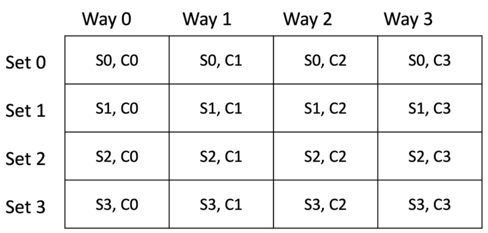
Figure 2 Hardware Cache
Let’s consider a memory area that can used to create a pool of buffers. Each buffer is 128 bytes, hence occupies 2 cache lines. Assuming the first buffer address starts at 0x0, the addresses of the buffers are as shown below.
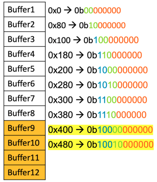
Figure 3 Contiguous buffers in memory
In the above figure the offset bits are highlighted in orange, set bits in green and tag bits in blue. Consider buffer 1’s address, where set bits “00” means the buffer maps to set0. Assuming initially all the sets are empty, buffer 1 occupies the first cache line of 2 contiguous sets.
Since buffer 1 address is 0x0 and the cache line size is 64 bytes, the first 64 bytes of the buffer occupy the cache line in set0. For the next 64 bytes, the address becomes 0x40 (0b01000000) indicating set1 because the set bits are “01”. As a result, the last 64 bytes of the buffer occupy the cache line in set1. Thus, the buffer is mapped into cache lines (S0, C0) and (S1, C0).
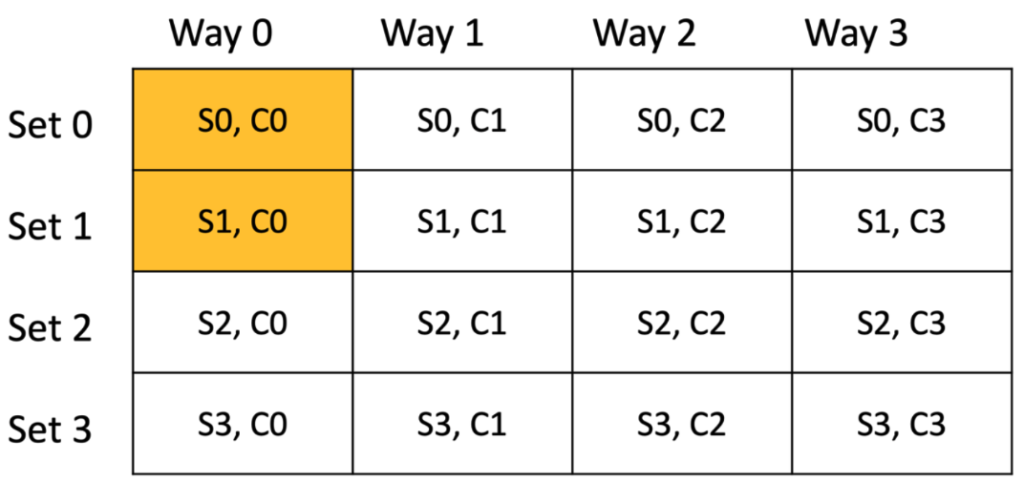
Figure 4 Hardware cache with buffer 1
Similarly, buffer 2 will occupy the first cache line of next two sets (S2, C0) and (S3, C0).
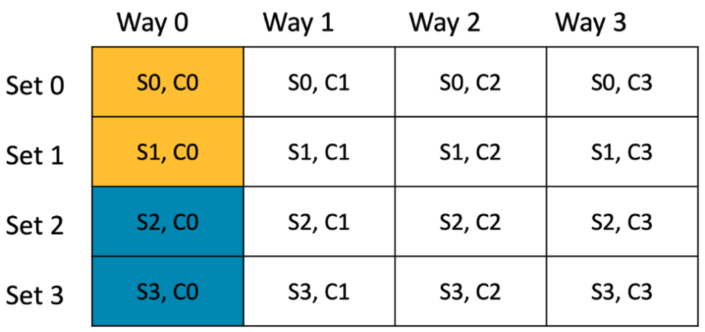
Figure 5 Hardware cache with 2 buffers
The set bits in buffer 3 address “00” show that the buffer 3 maps to set 0 again. Since the first cache line of set0 and set1 is occupied, buffer 3 occupies second cache line of set 0 and 1 (S0, C1) and (S1, C1).
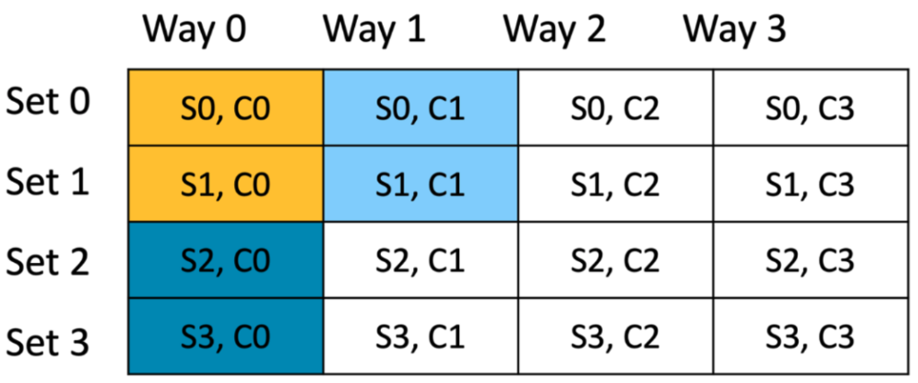
Figure 6 Hardware cache with 3 buffers
Similarly buffer 4 occupies the second cache-line of sets 2 and 3 and so on. Each buffer is represented with a different color and a total of 8 buffers can occupy the hardware cache without any evictions.
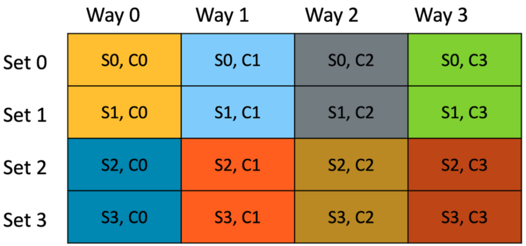
Figure 7 Allocation of buffers in hardware cache
Although the buffer size is 128 bytes, CPU might not access all the bytes. For example, for 64 bytes packets, only the first 64 bytes of the buffer are consumed by the CPU (i.e. one cache line worth of data).
Since the buffers are two cache lines long, and are contiguous, and only the first 64 bytes of each buffer is accessed, only sets 0 and sets 2 are populated with data. Sets 1 and 3 go unused (unused sets are shown with pattern in Figure 8).
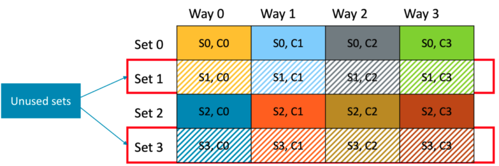
Figure 8 Unused sets in hardware cache
When buffer 9 needs to be cached, it maps to set 0 since set bits are “00”. Considering a LRU replacement policy, the least recently used cache line of 4 ways (buffer 1, 3, 5 or 7) in set0 will be evicted to accommodate buffer 9 even though set 1 and set 3 are empty.
This is highly inefficient, as we are not utilizing the cache capacity to the full.
Solution – Allocation of buffers with Cache awareness
In the above example, if the ununsed cache sets can be utilized to allocate the subsequent buffers (buffers 9 – 16), we would utilize the cache in a more efficient manner.
To accomplish this, the memory addresses of the buffers can be manipulated during the creation of mempool. This can be achieved by inserting one cache line padding after every 8 buffers, effectively aligning the buffer addresses in a way that utilizes the cache more efficiently. Let’s take the above example of contiguous buffer addresses and then compare it with same buffers but with cache line padding.
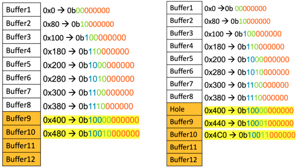
Figure 9 Without cache lines padding Figure 10 With cache lines padding
From figure 9 and 10, we can see that the buffer 9 address has changed from 0x400 to 0x440. With 0x440 address, the buffer 9 maps to set1. So, there is no need to evict any cache line from set0 and we are utilizing the unused cache set 1.
Similarly, buffer 10 maps to set3 instead of set2 and so on. This way buffer 9 to buffer 16, can occupy the sets1 and 3 that are unused by buffers1 to 8.
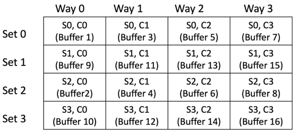
Figure 11 Hardware cache with cache awareness
This approach effectively distributes the allocation of buffers to better utilize the hardware cache. Since for 64-byte packets, only the first cache line of each buffer contains useful data, we are effectively utilizing the hardware cache capacity by accommodating useful packet data from 16 buffers instead of 8. This doubles the cache utilization, enhancing the overall performance of the system.
Padding of cache lines is necessary primarily when the cache size is exactly divisible by the buffer size (which means buffer size is a power of 2). In cases where the buffer size does not divide evenly into the cache size, part of the buffer is left unmapped. This residual portion effectively introduces an offset like the one achieved through padding.
Cache Awareness in DPDK Mempool
In DPDK mempool, each buffer typically has a size of 2368 bytes and consists of several distinct fields – header, object and trailer. Let’s look at each one of them.
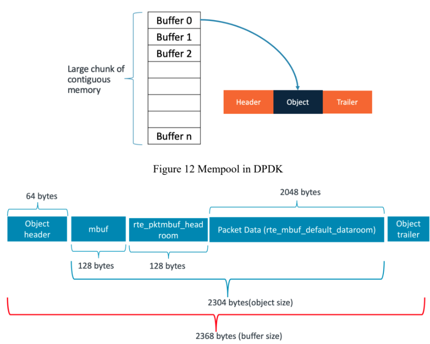
Figure 13 Mempool buffer fields
Header: This portion of the buffer contains metadata and control information needed by DPDK to manage buffer efficiently. It includes information such as buffer length, buffer state or type and helps to iterate on mempool objects. The size of the object header is 64 bytes. Object: This section contains actual payload or data. Within the object section, there are additional fileds such as mbuf, headroom and packet data. The mbuf of 128 bytes contains metadata such as message type, offset to start of the packet data and pointer to additional mbuf structures. Then there is a headroom of 128 bytes. The packet data is 2048 bytes that contains packet headers and payload.
Trailer: The object trailer is 0 bytes, but a cookie of 8 bytes is added in debug mode. This cookie acts as a marker to prevent corruptions.
With a buffer size of 2368 bytes (not a power of 2), the buffers are inherently aligned with cache awareness without the need for cache line padding. In other words, the buffer size is such that it optimizes cache utilization without the need for additional padding.
The buffer size of 2368 bytes does not include the padding added to distribute buffers across memory channels.
To prove how the performance can vary with a buffer size that is power of 2, I ran an experiment with 2048 buffer size and compared it against the default buffer size of mempool in DPDK. In the experiment 8192 buffers are allocated in the mempool and a histogram of cache sets for all the buffers was plotted. The histogram illustrates the number buffers allocated in each cache set.
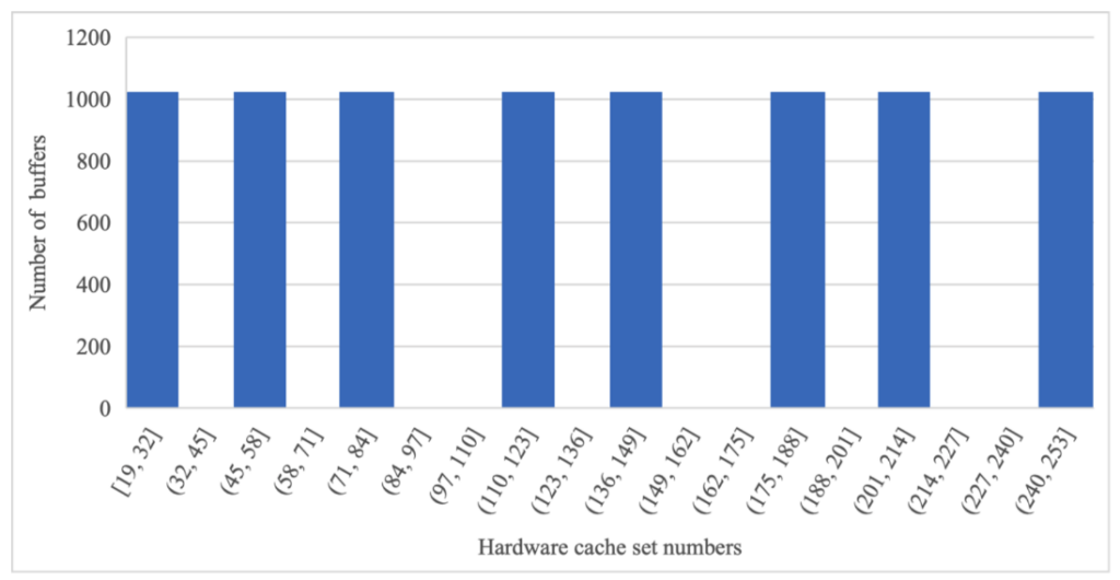
Figure 14 Histogram of buffers – 2048 bytes
With a buffer size of 2048 bytes, the same sets in the hardware cache are hit repeatedly, whereas other sets are not utilized (we can see that from the gaps in the histogram)
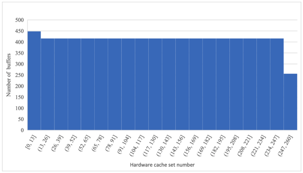
Figure 15 Histogram of buffers – 2368 bytes
With a buffer size of 2368 bytes, each set is being accessed only around 400 times. There are no gaps in the above histogram, indicating that the cache is being utilized efficiently.
DPDK l3fwd Performance
The improved cache utilization observed in the histogram, attributed to cache awareness, is further corroborated by the throughput numbers of the l3fwd application. The application is run on a system with 64KB 4-way set associative cache.
Below chart shows the throughput in MPPS for single core l3fwd test with 2048 and 2368 buffer sizes
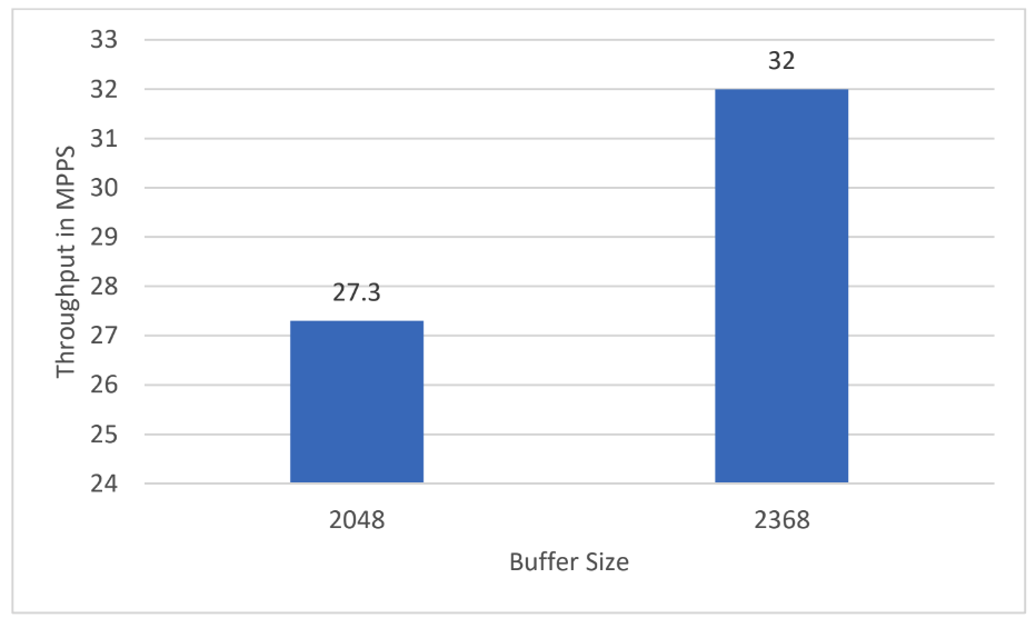
Figure 16 l3fwd throughput comparison
There is a 17% performance increase with the 2368 buffer size.
Conclusion
Contiguous buffer allocation in memory with cache awareness enhances performance by minimizing cache evictions and maximizing hardware cache utilization. In scenarios where the buffer size is exactly divisible by the cache size (e.g., 2048 bytes), padding cache lines creates a offset in the memory addresses and better distribution of buffers in the cache. This led to a 17% increase in performance for DPDK l3fwd application.
However, with buffer sizes not precisely divisible by the cache size, as is the default in DPDK, padding of cache lines already occurs because of the offset in the buffer addresses, resulting in an improved performance.
For more information visit the programmers guide

